
Home
- LEDsaddremove
- Componentsaddremove
- Power suppliesaddremove
- LED strips
- LED modules
- Aluminum profiles and accessoriesaddremove
- LED, CCFL rings
- Lampsaddremove
- Car bulbsaddremove
- Accessoriesaddremove
- Smart homeaddremove
- Shielding technologyaddremove
- Metal fireplaces


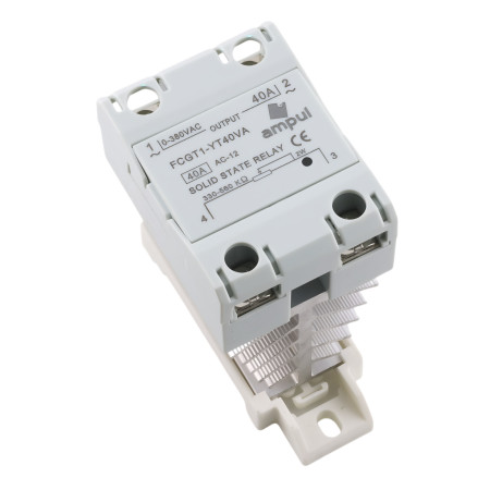


Contactless voltage regulator SSR VA with cooling, 500kOhm/0-380VAC
SSR (Solid State Relay) is an electronic relay with no moving parts that is used to control electrical circuits. Unlike traditional electromechanical relays that use an electromagnetic field to control contacts, SSR uses semiconductor elements such as transistors, thyristors or triacs to control electrical circuits. SSRs can be used to control power devices such as lights, heating systems, motor controllers, electric pumps and other electronic devices that require switching or regulating high power. SSRs are popular for their reliability, high switching speed, quiet operation and easy integration with other electronic components.
Contact cover
DIN rail mounting
Aluminum cooling, for switching currents above 40A, we recommend installing a fan in the distribution board.
Off time: ≤10ms
Voltage drop: ≤1.5V
Working temperature: -30 - +75°C
Insulation resistance: 1000MOhm
Control current: 25mA
Weight: 10A, 25A (170g). 40A (180g), 60A, 80A (291g), 100A, 102A (332g)

- Resistance
- 500 kOhm
- Output voltage
- 0-380 V AC
- Waterproof grade
- IP22
- Construction
- DIN
- Insulation resistance
- 1000 MΩ
- Dielectric strength
- 2500 V AC
This guide describes how to correctly connect an SSR electronic relay for AC voltage regulation (0–250 V AC) using a panel potentiometer LA42DWQ-22 (2 W). The wiring is suitable for controlling motors, heating elements, or lights.
SSR Terminal Designation
- Terminal 1 – AC IN (L) – input phase of the AC voltage
- Terminal 2 – AC OUT (L′) – output phase to the load
- Terminal 3 – potentiometer (Z1) – outer lead of the potentiometer
- Terminal 4 – potentiometer (Z2) – middle lead (wiper) of the potentiometer
Wiring of the LA42DWQ-22 Potentiometer
- Z1 (outer terminal) – connect to terminal 3 of the SSR
- Z2 (middle – wiper) – connect to terminal 4 of the SSR
- Z3 (other outer terminal) – usually not used in this application (leave unconnected)
Connection Steps
- Step 1: Make sure the circuit is disconnected from the mains.
- Step 2: Connect the 230 V AC power supply:
- L to terminal 1 (AC IN)
- Load (device) between terminal 2 (AC OUT) and N
- Step 3: Connect the potentiometer:
- Z1 → terminal 3 on SSR
- Z2 → terminal 4 on SSR
- Step 4: Mount the potentiometer into the panel hole (Ø 22 mm).
- Step 5: Check all connections, power on, and adjust the output voltage of the SSR by turning the LA42DWQ-22 knob.
Safety Warnings
- SSR with a current above 10 A must be equipped with a heat sink.
- Use wires with an appropriate cross-section.
- Include a fuse or circuit breaker in the circuit.
- The wiring must be performed only by a qualified person.
EU Importer: AMPUL SYSTEM s.r.o., Čsl. armády 641/40, 78701 Šumperk, Czech Republic,
 for SSR relays on 35 mm DIN rail")


