
Home
- LEDsaddremove
- Componentsaddremove
- Power suppliesaddremove
- LED strips
- LED modules
- Aluminum profiles and accessoriesaddremove
- LED, CCFL rings
- Lampsaddremove
- Car bulbsaddremove
- Accessoriesaddremove
- Smart homeaddremove
- Shielding technologyaddremove
- Metal fireplaces


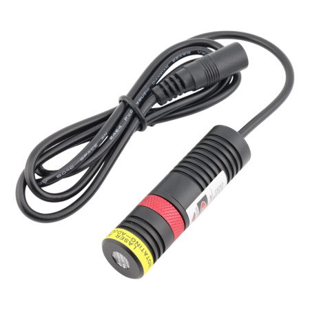


Laser module red 650nm, circle with cross
Red laser module (650nm), power from 10mW to 200mW.
⚠️ Safety warning: This laser module is an electronic component intended exclusively for professional, laboratory, and industrial applications. It is not intended for consumer or household use and must not be used as a laser pointer.
During operation, it is necessary to comply with the safety requirements of the EN 60825-1 standard and to use appropriate protective equipment. The manufacturer of the final device is responsible for the resulting laser classification according to EN 60825-1.
The red 650nm laser module with a circle and cross projection is designed for aiming, positioning and optical guidance applications in industry, measurement technology and integration into devices. The module uses DOE optics with adjustable focus and is powered by 5V DC. The metal aluminum housing supports heat dissipation and ensures mechanical resistance during normal operation.
Technical specifications
- Product type: laser module with circle projection with cross
- Laser color: red
- Wavelength: 650nm
- Case dimensions: Ø18 x 65mm
- Housing material: aluminum
- Lens type: PMMA
- Optics type: DOE
- Focus: adjustable
- Operating mode: APC/ACC
- Supply voltage: 5V DC
- Connection: 1m cable with DC connector 5.5/2.1mm
- Working temperature: -10 to +50°C
- Storage temperature: -40 to +85°C
- Mean time to failure: more than 8000 hours
Real optical power table
| Rated power | Real optical performance |
| 10mW | 7.5 to 8.5 mW |
| 30mW | 18 to 24mW |
| 50mW | 38 to 45mW |
| 100mW | 75 to 95 mW |
| 150mW | 100 to 120 mW |
| 200mW | 130 to 150 mW |
Functions and features
- Circle projection with crosshairs for precise optical aiming
- 650nm red laser suitable for general visual guidance and indication
- DOE optics for creating a defined pattern
- Adjustable focus to adapt projection to specific distance and application
- Aluminum body for better thermal stability and mechanical resistance
- 5V DC power supply for easy integration into devices and test benches
- APC and ACC operating modes for corresponding laser diode control
Ideal for
- Industrial surveying and positioning
- Production line guidance systems
- Optical marking of reference points
- Integration into measuring and control devices
- Laboratory and development applications
- Adjusting, setting up and checking geometry
Package contents
- 1x laser module red 650nm, circle with cross
- 1x connection cable 1m with DC connector 5.5/2.1mm
Why choose this product?
- Combination of compact dimensions and robust metal design
- Clearly defined circle and cross projection pattern for technical applications
- Clearly specified nominal and real optical power values
- Standard 5V DC power supply and ready-made cable connection
- Suitable solution for integration into industrial, laboratory and development systems
Installation and operating instructions
- During installation, ensure a firm mechanical attachment of the module without vibration transmission.
- For proper operation, it is necessary to use a stabilized 5V DC power supply.
- After installation, adjust the focus according to the desired working distance and the size of the projected image.
- During long-term operation, we recommend ensuring adequate heat dissipation according to the selected power variant.
- Use the module within the specified operating temperature range.
Safety notice
- Laser radiation can be dangerous to your eyesight.
- Do not look directly into the output beam or at its reflection from shiny surfaces.
- When integrating into a device, we recommend using appropriate protective measures corresponding to the module's power variant.
- The product is not intended for use without appropriate technical assessment in applications where failure could result in a risk to health or property.

- Light color
- Red
- Wavelength
- 650 nm
- Voltage
- 5 V DC
- Cable length
- 100 cm
- Connector
- 5.5x2.1 mm
- Waterproof grade
- IP20
- Lifetime
- 8,000 hours
- Appearance
- Circle with a cross
Introduction
This manual provides instructions for the safe use and regular maintenance of laser modules designed for projecting indicators (lines, crosses, dots, and DOE/grids) with a maximum output of up to 2000 mW. The document also includes the definition of a safety zone based on tabulated values that determine the distance at which the exposure is classified as Class 3B (higher risk) and from which it is classified as Class 3R (lower risk).
1. Understanding the Risks of Laser Radiation
- Eye Damage – Direct and reflected laser radiation can cause permanent retinal damage.
- Skin Burns – An intense beam may cause burns with prolonged exposure.
- Mechanical Risk – Improper handling of optical components (lenses, mirrors, DOE) may lead to their misalignment or damage, increasing the concentration of emitted energy.
- Accidental Activation – Service interventions without proper disconnection from power or violation of safety measures may result in unintended laser activation.
2. Overview of Safety Classes and Necessary Precautions
- Class 2
- Low-power lasers (usually up to 1 mW) – safe during brief exposure due to the blink reflex.
- Warning labels indicating not to look into the beam.
- Adherence to safety procedures to prevent accidental increases in exposure.
- Class 3R
- Lasers with slightly higher power (up to several mW) – direct viewing may cause damage, but the risk is relatively lower.
- Output apertures are marked with warning labels.
- Strict adherence to safety distances to ensure exposure remains at Class 3R levels.
- Class 3B
- High-power lasers where direct exposure to the beam can cause immediate and permanent eye damage.
- Requirement for a key switch to prevent accidental activation.
- Implementation of a remote interlock system (e.g., door switch or emergency button).
- Visible activity indicator (“Laser On”) and requirement to wear protective goggles during service interventions.
- Class 4
- The highest power level, where even scattered radiation poses extreme danger to eyes and skin.
- Prominent warning labels and markings, a key switch, interlock system, and mechanical beam shutter.
- The device must have a manual reset after each interruption of operation, and operation is permitted only by qualified personnel in designated areas.
3. Definition of the Safety Zone
The safety zone is defined using a table that specifies:
- Controlled Zone (3B): The area from the device up to a distance of X meters, where the exposure corresponds to Class 3B. Only trained users have access to this zone, and strict measures apply (key switch, interlock, mandatory protective goggles).
- Restricted Zone (3R): The area beyond X meters, where the exposure drops to Class 3R. Basic safety measures, such as area marking and physical barriers, must also be observed here.
Note: The value of X should be determined using the available calculator. Physical marking of the safety zones (floor, wall signs, etc.) is mandatory.
4. Proper Handling of the Product
- Before Activation – Place the device in a stable location where the safety zone is clearly defined. Verify that all safety features (key switch, interlock, protective covers) are functioning properly.
- During Operation – Adhere to the safety zones. Never enter the controlled zone (3B) without appropriate training and protective gear. Ensure that unauthorized personnel do not enter areas with high exposure.
- During Handling and Service – Before any service intervention, completely turn off the device and disconnect it from the power supply. Do not remove or modify any safety features or protective covers.
5. Maintenance and Service
- Regular Inspections – Perform visual and functional checks of the optical components and safety covers. Verify the proper operation of interlock systems, the key switch, and indicators.
- Cleaning – Clean optical components (lenses, mirrors, DOE) only with approved cleaning agents and a soft cloth (preferably microfiber) in a controlled environment.
- Service and Calibration – If deviations in projection or other functional issues are detected, contact an authorized service provider. Document all service interventions and calibrations.
6. Emergency Procedures
- In Case of Malfunction – Immediately turn off the device and disconnect it from the power supply. Prevent unauthorized access to the safety zone and record a description of the malfunction. Contact an authorized service provider.
- In Case of Accidental Exposure – Immediately stop the exposure (turn off the device, leave the beam area). If there is any suspicion of eye or skin injury, provide first aid and seek medical assistance. Document the incident properly.
7. Conclusion and Recommendations
By following the above procedures, you ensure safe operation and minimize the risks associated with laser radiation. A proper definition of the safety zone based on tabulated values (controlled zone 3B and restricted zone 3R) allows for clear delineation of areas where stricter measures must be observed, and provides users with clear instructions for safe handling of the product.
We recommend a regular review and update of the documentation according to changes in operating conditions and personnel training.
EU Importer: AMPUL SYSTEM s.r.o., Čsl. armády 641/40, 78701 Šumperk, Czech Republic,


