
Home
- LEDsaddremove
- Componentsaddremove
- Power suppliesaddremove
- LED strips
- LED modules
- Aluminum profiles and accessoriesaddremove
- LED, CCFL rings
- Lampsaddremove
- Car bulbsaddremove
- Accessoriesaddremove
- Smart homeaddremove
- Shielding technologyaddremove
- Metal fireplaces


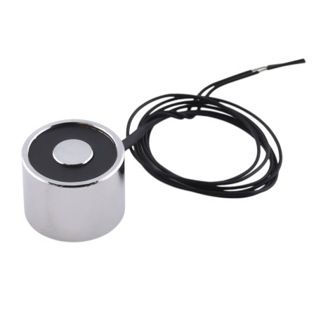


Electromagnet 2.5kg, 25N, 20x15mm
Fully encapsulated industrial quality electromagnet.
Holding force 2.5kg / 25N
3W power
limit temperature 103°C
size 20x20x15 mm
thread size M4
cable length 200 mm
price for 1 pc
The adhesive surface must be cleaned before first use

- Performance
- 3 W
- Thread
- M4
- Holding force
- 25 N
- Waterproof grade
- IP65
- Type
- Magnetizing
1. Define Application Requirements
-
Purpose of Use:
- Determine whether the electromagnet will be used for door securing, load holding, or automation.
- Specify which object and what weight will be held.
-
Operating Environment:
- Evaluate the temperature conditions – in enclosed machine compartments significant heating may occur.
- Consider additional factors such as vibrations, dust, or humidity.
-
Safety Margins:
- Define the required holding force (in newtons) with sufficient reserve to ensure reliable operation even under deviations.
2. Define Technical and Electrical Parameters
- Supply Voltage:
- Identify the available voltage (e.g., 3 V, 5 V, 6 V, 12 V, 24 V, 36 V) and choose an electromagnet that matches this voltage.
- Current and Power:
- Verify that at the given voltage the device generates sufficient current to produce the required magnetic field.
- Be aware that excessive voltage may cause increased coil heating (according to P = I²R), which can affect performance.
3. Select the Type of Electromagnet
Choosing the right type of electromagnet is crucial, as its behavior (magnetic force, switching speed, thermal stability) varies significantly depending on the construction. At this stage, consider the following aspects:
3.1. Magnetizing vs. Demagnetizing Electromagnets
-
Magnetizing Electromagnets (standard type):
- Principle: When current is applied, the coil is energized, creating a magnetic field. This field attracts ferromagnetic material (e.g., an armature), closing the magnetic circuit.
- Applications: Used in security systems, load holding, or locking mechanisms where firm holding is required during active operation.
- Operation: They hold stably while powered. Once the current is removed, the magnetic force is lost, which is important when designing the control system.
-
Demagnetizing Electromagnets:
- Principle: These are designed so that their magnetic field is “suppressed” during normal operation – they become magnetically active only when the power is disconnected. In other words, in the powered state attraction is minimized, and once current is cut off, the magnetic field is released to attract the object.
- Applications: Often used in locking systems where doors or other elements should automatically release in emergencies (e.g., power outage). This principle is also used in bistable electromagnets, where one state is maintained by a permanent magnet and the other – when current is applied – is temporarily disrupted.
3.2. Other Design Variants and Specifics
-
Solenoid Electromagnets:
- Structure: Composed of a wound coil and a movable part (armature or plunger) that is drawn toward the coil when current flows.
- Response Speed: Solenoid electromagnets often respond very quickly, which is important in industrial automation or electromagnetic locks.
- Control Capability: Their design allows precise control of activation and deactivation times, useful in applications requiring accurate release or holding timing.
-
Variable Magnetic Force Control:
- Some modern systems allow current modulation, enabling real-time control of magnetic force. This is useful when application conditions change (e.g., gradual heating of the electromagnet during long-term use).
- A control unit can be integrated directly into the system, adjusting supply current using sensors (e.g., temperature measurement) to maintain constant holding force.
-
Combined Solutions with Permanent Magnets:
- In some applications, permanent magnets are added to electromagnets to create a bistable state. In this setup, the electromagnet holds even without power – switching current allows quick release, suitable for safety or emergency release mechanisms.
3.3. Integration Options and System Compatibility
- Control Signals:
- Ensure the selected electromagnet type is compatible with your control system, including switching, current modulation, timing, and integration with safety elements.
- Modulation and Precision:
- For applications requiring precise control of magnetic field intensity (e.g., differential attraction control), choose electromagnets with current modulation capability. This feature enables accurate and adjustable magnetic force according to application needs.
3.4. Summary and Selection Recommendations
When selecting an electromagnet type, consider the following:
- If the device must hold an object firmly while powered, choose magnetizing electromagnets.
- If your application requires release upon power cut (e.g., for safety reasons), choose demagnetizing or bistable electromagnets.
- Also account for response speed and precise control of magnetic force if critical.
- Finally, verify integration with your control system for proper operation and monitoring in real conditions.
4. Thermal Management
-
Expected Heating:
- Electromagnets commonly heat up in operation. Some models may reach surface temperatures of about 100 °C.
- Follow manufacturer specifications for maximum operating temperature.
-
Overheating Protection:
- If high thermal loads are expected, consider additional cooling (fans, passive heatsinks, or even liquid cooling) to keep the coil surface within the recommended range.
5. Material and Design Aspects – Focus on the Armature
The armature is a key part of the electromagnet, closing the magnetic circuit and strongly influencing holding force. Details:
5.1. Suitable Materials
-
Soft Iron and Low-Carbon Steels:
- These materials have high magnetic permeability and low coercivity, allowing magnetic flux with minimal loss.
-
Electrical (Silicon) Steel:
- Silicon reduces eddy current and hysteresis losses, improving overall efficiency.
-
Special Ferromagnetic Alloys:
- Examples: permalloy or supermalloy, offering very high permeability, though limited by higher cost or mechanical constraints.
5.2. Unsuitable Materials
-
Austenitic Stainless Steels:
- Usually non-magnetic or low permeability, making them unsuitable for armatures.
-
Non-Ferromagnetic Metals (Aluminum, Copper):
- Since they are not ferromagnetic, they cannot effectively conduct magnetic flux.
-
Materials with Unfavorable Impurities:
- High carbon content or undesirable elements (chromium, manganese, copper in wrong ratios) can reduce magnetic conductivity.
5.3. Ideal Armature Thickness and Calculation
The aim is to close the magnetic circuit efficiently. Magnetic reluctance is given by:
R_air = δ⁄(μ₀A) and R_m = T⁄(μA)
where:
- δ = minimum air gap
- T = armature thickness
- A = contact area
- μ₀ = 4π×10⁻⁷ H/m = vacuum permeability
- μ = μ_r·μ₀ = absolute permeability of the armature material
To ensure material reluctance is much lower than air gap reluctance:
T ≪ (μ/μ₀)·δ
Example Calculation:
If relative permeability μ_r ≈ 2000 and air gap δ = 0.1 mm (1×10⁻⁴ m):
(μ/μ₀) = μ_r ≈ 2000
T ≪ 2000 · 1×10⁻⁴ m = 0.2 m
This shows armature thickness may reach tens of millimeters theoretically. In practice, small/medium electromagnets use 2–5 mm, balancing magnetic closure and mechanical stability. Larger designs may use 10–20 mm. Final values depend on application and geometry.
6. Integration and Mounting Requirements
- Mounting:
- Ensure firm, accurate positioning so that contact surfaces (armature and electromagnet) align perfectly, minimizing air gap.
- Control and Operation:
- Verify compatibility with your control system and accurate switching timing, especially for repetitive cycles and temperature monitoring.
7. Testing and Validation
- Laboratory Tests:
- Before final installation, measure holding force under realistic operating conditions, including thermal cycles, to confirm compliance with specifications.
- Operational Simulations:
- Simulate coil heating and verify holding force remains above the required value and material or insulation does not degrade.
8. Design Review and Optimization
- Analysis of Test Results:
- If problems occur (e.g., excessive heating, reduced magnetic force due to improper armature thickness), adjust the design.
- Consultation with Manufacturer:
- If uncertain about material or design parameters, contact technical support or the manufacturer for optimization.
1. What is a holding electromagnet and how does it work?
- A holding electromagnet is an open magnetic circuit that, when supplied with direct current, generates a magnetic field attracting a ferromagnetic object to the active pole surface. When the power is turned off, it loses most of its strength and no longer holds the armature (except for minimal remanence).
2. What materials can be held by a holding electromagnet?
- Electromagnets attract only ferromagnetic materials with a high iron content, such as low-carbon steel. Metals like aluminum, brass, or gold are unsuitable, as they are not affected by magnetic fields.
3. How is the holding force specified and measured?
- The holding force is expressed as the weight or force the magnet can support in a suspension test. The measurement is performed on a standard steel armature 0.250″ (≈6.35 mm) thick, testing only the axial separation force without the influence of shear forces.
4. How does the air gap affect performance?
- Even a thin layer of dirt, paint, or surface irregularities between the pole and armature creates an air gap, which exponentially increases magnetic reluctance and drastically reduces holding force. Full contact and clean, smooth surfaces are therefore crucial for optimal performance.
5. Why does the electromagnet heat up and how to prevent it?
- The electromagnet heats up due to Joule losses in the coil (P = I²·R). To reduce heating, you can:
- use more turns with lower current (lower I²R losses) or thicker wire,
- operate intermittently (duty cycle) to allow cooling,
- mount on a metal heatsink or provide ventilation.
6. What is a duty cycle and how to choose it?
- The duty cycle (ED – Einschaltdauer) expresses the percentage of time the magnet can be energized continuously without exceeding the maximum surface temperature (e.g., 25% ED means 1 min ON / 3 min OFF). For 100% ED, a magnet with better thermal capacity or active cooling is required.
7. How to protect the coil and electronics from voltage spikes?
- When the current is switched off, the inductive winding generates high voltage spikes. To limit them, use:
- a flyback (freewheeling) diode connected in parallel with the coil,
- or alternatively, an RC snubber or transil suppressor.
8. What are demagnetizing (energize-to-release) types used for?
- Demagnetizing models, after switching off:
- actively invert polarity (reverse pulse),
- use RLC resonance to neutralize residual magnetization.
9. What is the difference between fail-safe and fail-secure types?
- Fail-safe (power-to-hold): Holds only when powered; releases when power is lost – suitable for emergency door locks or safety applications.
- Fail-secure (power-to-release): Remains held even without power (e.g., electropermanent magnets); releases only after an active pulse – ideal for lifting and retaining applications where unexpected release must be prevented.
10. How to perform installation and maintenance?
-
- Cleanliness and flatness of surfaces: Before installation, clean the contact surface from dust, oil, and rust.
- Direct contact: The magnet and armature must meet evenly without lateral forces.
- Regular inspection: Check coil insulation, mounting tightness, and contact cleanliness, especially in dusty or oily environments.
EU Importer: AMPUL SYSTEM s.r.o., Čsl. armády 641/40, 78701 Šumperk, Czech Republic,


